Choosing carbon fiber for aerospace applications requires more than praising its low weight. Engineers must connect material data with real aircraft demands. The keyword “what makes carbon fiber suitable for aerospace applications” points to a practical balance: high specific strength, stiffness, fatigue resistance, corrosion resistance, and design flexibility. Carbon fiber reinforced polymer can reduce structural mass while supporting slender wings, pressure vessels, control surfaces, and cabin components.
Boeing’s former vice president Mike Sinnett described the 787 Dreamliner as “made of 50 percent composite materials.” That figure shows the material’s industrial credibility, not automatic suitability. Each application still needs careful assessment. Fiber direction matters. Resin selection matters. So do impact tolerance, moisture exposure, lightning protection, repair methods, and manufacturing quality. A thin carbon-fiber panel may look impressive on a test bench. It may behave differently after repeated thermal cycles and minor impact damage.
A reliable selection process begins with the aircraft mission. Engineers should compare tensile strength, compression performance, interlaminar toughness, density, and certified process data. They should also examine production consistency and inspection requirements. In my experience, the strongest datasheet rarely tells the whole story. That is the uncomfortable part. Carbon fiber is not universally superior. Poor layup control, hidden voids, or an unsuitable resin can erase its advantages. The right choice is therefore a tested material system, not simply a premium fiber grade. This guide will examine those trade-offs, using aerospace engineering practice rather than marketing language.
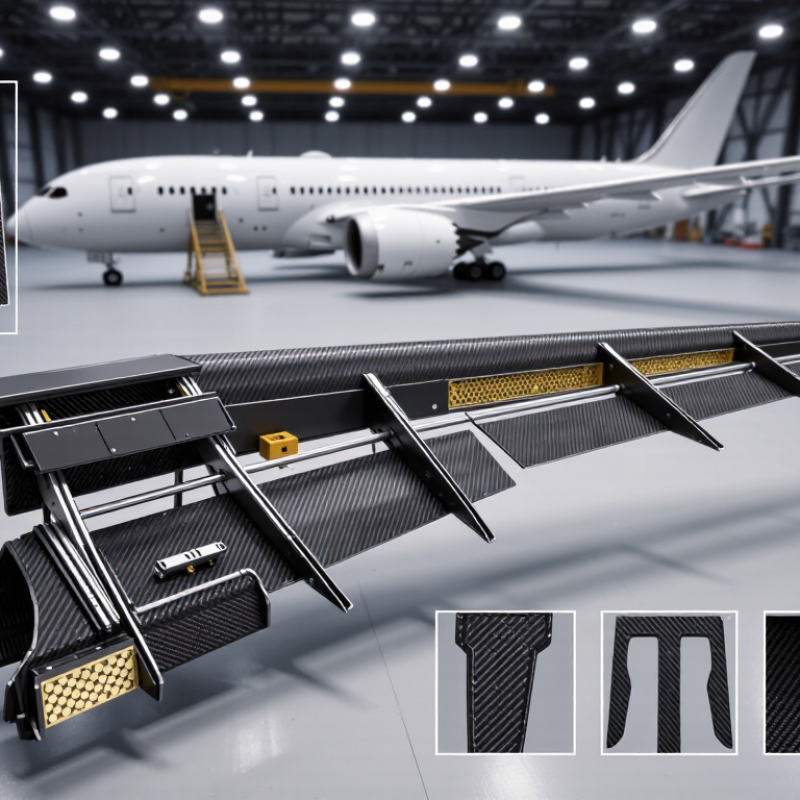
Aerospace carbon fiber is selected by property balance, not maximum strength alone. Standard-modulus PAN-based fiber usually offers tensile modulus near 230–250 GPa and density around 1.75–1.90 g/cm³. Intermediate-modulus grades can exceed 290 GPa, improving stiffness in wings and control surfaces. High-modulus fiber may reach 500 GPa or more, but it often sacrifices strain-to-failure and impact tolerance. These ranges are reported in CMH-17 composite material data. Pitch-based fiber provides excellent thermal conductivity, while PAN-based fiber remains more common in structural laminates.
The laminate matters as much as the fiber. Aerospace engineers examine tensile strength, compression strength, interlaminar toughness, fatigue behavior, moisture uptake, and thermal expansion. FAA AC 20-107B stresses substantiation through testing, inspection, and damage-tolerance analysis. A lighter panel is not automatically safer. A brittle, high-modulus option can perform poorly after a tool drop or barely visible impact. Real programs also consider curing temperature, fiber areal weight, automated placement accuracy, and repair access. The decision is rarely perfect. Early test assumptions may need revision.
Tips: Match fiber modulus to load paths, then verify compression and impact data. Ask for batch-level certificates, not only brochure averages. Use coupon, element, and full-scale testing. Include moisture and temperature conditioning. A spreadsheet can look precise, yet manufacturing variation still changes performance.
Choosing carbon fiber for aerospace begins with a load map, not a material catalog. Define tensile, compression, shear, bending, fatigue, and impact demands for each component. A wing skin faces different stresses than a seat frame. Record peak loads, load cycles, and acceptable deformation. Include joints. Fastener holes often govern real-world failure.
Start with the structure. Fiber direction, laminate thickness, and resin toughness should follow the load path. High stiffness may reduce deflection, but it can increase brittleness and damage sensitivity. Engineers should review strain limits, buckling margins, and crack-growth assumptions through validated analysis and representative testing.
Operating conditions can change the material decision. Map temperature extremes, pressure changes, moisture, ultraviolet exposure, fluids, vibration, and acoustic loads. A laminate tested at room temperature may behave differently after thermal cycling and absorbed moisture. Consider storage, ground handling, maintenance, and emergency landing loads. Test the ugly cases. A dropped tool can create barely visible damage, reducing compression strength. Choose toughening strategies and inspection methods that match maintenance reality. If inspectors cannot detect defects reliably, the design assumption is weak. Manufacturing constraints deserve equal attention. Confirm allowable void content, cure variation, ply placement accuracy, and repair procedures. A theoretically efficient laminate may become unreliable when production tolerances widen. Use coupon, element, and full-scale testing to correlate models with physical behavior. Some choices remain uncertain. Revisit early selections after test data arrives, and record the uncertainty beside the design decision.
Choosing carbon fiber for aerospace work begins with load paths, not catalog strength. In design reviews, I compare four properties: tensile strength, stiffness, weight, and damage tolerance. Strength resists final failure. Stiffness limits bending, vibration, and deflection. They are not interchangeable. A very strong laminate can still flex too much around a thin panel.
High-modulus fibers provide greater stiffness at similar density, which can reduce thickness and save space. However, they may cost more and tolerate impact less gracefully. High-strength fibers often suit heavily loaded tension members, but the laminate also depends on fiber direction, resin quality, and void content. Weight must be measured at system level. A lighter skin may require ribs, fasteners, or local doublers. The aircraft can become heavier. That happens.
Damage tolerance deserves physical thinking. Picture a tool dropped near a panel edge, leaving a shallow dent that looks harmless. Ultrasonic inspection may reveal internal delamination. Tougher architectures, balanced layups, and suitable hybrid plies can slow damage growth. I would verify this through impact, compression-after-impact, fatigue, and environmental testing. Test data should match temperature, moisture, manufacturing process, and repair assumptions. Early coupon results can mislead. Real structures are less polite. Final selection should follow certified allowables and a documented design review, with safety factors appropriate to the part’s failure consequences.
Carbon fiber selection should begin with the manufacturing process, not only tensile strength. A unidirectional tape suits automated fiber placement and highly directional loads. Woven fabric works better around curves, although it may reduce straight-line stiffness. Tow size also affects placement accuracy, resin flow, and surface quality. In trial builds, small changes in fiber spread have altered void content more than expected.
Material compatibility is equally important. The fiber sizing must bond reliably with the selected epoxy or thermoplastic matrix. Check cure temperature, viscosity, moisture absorption, and thermal expansion before approving a material. A resin that flows well in a laboratory panel may behave differently during thick-section molding. That difference matters. Poor flow can trap air near fastener holes or internal corners.
The production route should match the component’s geometry and inspection plan. Autoclave curing can provide excellent consolidation, but it increases equipment and cycle demands. Resin transfer molding may improve repeatability for complex parts, yet permeability must be measured carefully. After curing, verify fiber volume, void percentage, interlaminar strength, compression after impact, and thermal cycling performance. Carbon fiber can also create galvanic corrosion when contacting aluminum, so isolation layers and compatible fasteners require testing. I would not rely on a single datasheet. Batch variation, handling damage, and imperfect cure control can quietly change performance. A qualified process, documented traceability, and realistic coupons provide stronger evidence than impressive headline values.
Certification should be checked before comparing prices. Request current certificates, material specifications, and lot-level traceability. Each roll or batch should connect to test records, production dates, and inspection results. A certificate alone is not enough. Ask who performed the testing and whether the laboratory uses controlled methods. In aerospace work, small documentation gaps can delay an entire build.
Quality control becomes visible in practical details. Review fiber alignment, resin content, void levels, surface condition, and curing records. Request sample data from several production lots, not one perfect report. Check how nonconforming material is isolated and investigated. I would also inspect packaging, because crushed edges and moisture exposure can damage otherwise qualified material. Simple checks matter.
Cost deserves a wider calculation. A cheaper material may create more scrap, slower layup, or repeated testing. Compare usable material cost, lead time, qualification effort, and storage requirements. Supply reliability needs evidence, too. Ask about normal capacity, backup equipment, inventory policies, and communication during shortages. I have seen purchasing plans rely on optimistic delivery dates. That was a mistake. Keep an approved alternative, but qualify it before pressure arrives. Review supplier performance regularly, since yesterday’s reliable delivery does not guarantee tomorrow’s.
It supports many structural laminates. Its tensile modulus is usually about 230–250 GPa, with density near 1.75–1.90 g/cm³.
It can exceed 290 GPa. This added stiffness suits wings, control surfaces, and other parts needing limited deflection.
No. It may reach 500 GPa or more, but often sacrifices strain-to-failure and impact tolerance.
Fiber type is only one factor. Ply direction, thickness, resin toughness, void content, and joint design also matter.
They should map tension, compression, shear, bending, fatigue, impact, and deformation. Fastener holes deserve special attention.
Absorbed moisture and thermal cycling can change laminate behavior. Room-temperature data may not represent service conditions.
A dropped tool can create hidden damage. Compression strength may fall, even when the surface looks nearly normal.
Use coupon, element, and full-scale tests. Include temperature, moisture, impact, and manufacturing variations.
Request batch-level certificates, not only brochure averages. Record fiber properties, processing limits, and relevant test conditions.
Yes. Cure variation, ply-placement errors, and repair limits can reduce expected performance. Early assumptions may need revision.
Choosing carbon fiber for aerospace applications requires more than selecting the strongest material available. Engineers should first define the aircraft component’s structural requirements, load conditions, temperature range, moisture exposure, vibration, and expected service life. Different carbon fiber types and resin systems offer varying levels of tensile strength, stiffness, density, impact resistance, and damage tolerance. The best choice balances these properties while minimizing weight and maintaining reliable performance under demanding operating conditions. This balance explains what makes carbon fiber suitable for aerospace applications: its high strength-to-weight ratio, design flexibility, and potential for long-term durability.
Manufacturing considerations are equally important. The selected material must be compatible with processes such as automated fiber placement, resin infusion, or prepreg molding, while supporting consistent fiber alignment and void control. Engineers should also verify certification data, traceability, quality-control procedures, inspection methods, and environmental performance. Finally, cost, production scale, lead times, and supply reliability should be evaluated to ensure that the material is practical for both development and long-term aerospace production.

RAXIS Fiber