Designing carbon fiber parts for strength in China requires more than choosing a premium fabric. The real question is how to design carbon fiber parts for strength under actual loads, temperatures, and manufacturing limits. A lightweight bracket may face vibration, bolt pressure, moisture, and repeated impacts. Ignoring one detail can cause costly rework. This guide explores practical design decisions from concept development to production verification.
Experienced Chinese composite manufacturers usually begin with load paths, laminate orientation, and joint design. They then connect CAD decisions with tooling, resin systems, curing cycles, and inspection methods. A part that looks perfect can still hide dry spots, voids, poor consolidation, or fiber waviness. That is why reliable development uses prototypes, coupon tests, dimensional checks, and documented process controls. Factories may use vacuum infusion, compression molding, or autoclave curing, depending on volume and performance requirements. Each method changes strength, cost, surface quality, and production consistency. Small details matter.
In China, successful projects also depend on clear technical drawings and direct communication with suppliers. Specify fiber type, ply angles, tolerances, inserts, surface finish, and acceptance criteria. Ask for material certificates and test results, not attractive photographs. Independent verification can reveal gaps between laboratory strength and production performance. The discussion should remain practical and honest. Some early assumptions will be wrong. That is normal. Good design improves through measured evidence, supplier feedback, and controlled revisions. This approach supports stronger parts, stable quality, and safer decisions across the manufacturing process.
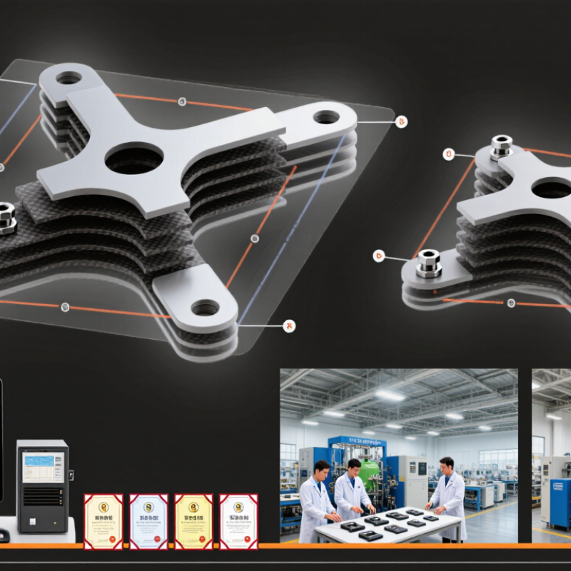
Define the strength requirement before choosing carbon fiber, resin, or laminate thickness. Start with the load. Record force, direction, duration, and frequency for every critical condition. A bracket may face tension, bending, torsion, or several loads at once.
Specify both the working load and the failure limit. Include a safety factor based on risk, uncertainty, and inspection quality. Static strength alone is rarely enough. Repeated loading can create fatigue damage, while a small impact may cause hidden delamination. Temperature, moisture, chemicals, and ultraviolet exposure can also reduce performance.
A neat spreadsheet can still mislead. I have seen designs pass a simple calculation but fail around holes, sharp corners, or poorly supported joints. Define allowable deflection as well as ultimate strength. For example, a panel might carry 2,000 newtons but still be unacceptable if it bends five millimeters.
Write the requirement in measurable terms. State the load case, test direction, temperature range, service life, and acceptable damage. Clarify whether the part must remain fully functional after impact or only avoid complete fracture. The manufacturing process in China should be considered early, because fiber orientation, resin content, voids, and dimensional tolerances affect real strength.
Use coupons, subassemblies, and full-size prototypes to verify assumptions. Test results should be traceable to material batches and production conditions. If the data disagrees with the model, revise the model rather than hiding the difference. Strength requirements should guide the design, not decorate the drawing.
Designing carbon fiber parts for strength in China begins with material selection, not a glossy surface. The 2023 Global Carbon Fiber Supply Chain Competitiveness Report estimated global carbon fiber demand at about 129,000 tonnes. China’s expanding electric vehicle and wind sectors are increasing pressure for lighter, durable structures. Choose standard-modulus fiber for balanced strength and cost. High-modulus fiber suits stiffness-critical beams, but it can be more brittle and expensive. A higher modulus is not automatically stronger.
Resin selection must match temperature, moisture, and production method. Epoxy usually provides strong fiber bonding and low shrinkage. For hot interiors or engine-adjacent parts, check the cured glass-transition temperature, not only room-temperature strength. Vacuum infusion may reduce cost, but void control becomes difficult. Autoclave curing can improve consolidation, yet it demands stricter process control. The International Energy Agency reported nearly 14 million electric cars sold globally in 2023, showing why repeatable lightweight production matters. Still, real workshop conditions can differ from laboratory results.
Tips: Align 0-degree plies with the main load. Add 90-degree plies for widthwise stability. Use ±45-degree plies for torsion and shear. Keep the laminate balanced and symmetric when possible. Avoid sudden thickness changes around bolt holes. I have seen failures begin at small edges, not the center panel. Test coupons from the actual Chinese production process, then review the layup after impact, humidity, and thermal cycling.
Designing a strong carbon fiber part in China starts with geometry, not material selection. Define how forces enter, travel, and leave the structure. A sharp corner can create stress concentration and cause premature cracking. Use generous radii around holes, ribs, and transitions. Keep load paths direct.
A practical part often needs local reinforcement. Add bonded inserts or thicker laminate around bolt holes, but avoid sudden stiffness changes. Taper extra plies gradually. Align fibers with the main tensile and compressive loads. For bending, place more material near the outer surfaces. For torsion, closed sections usually perform better than flat panels.
Manufacturing details must influence the design. Check draft angles, mold split lines, trimming access, and achievable laminate tolerances with the Chinese fabricator. A beautiful computer model may fail during layup. That happened in one trial because a narrow channel trapped air near a rib. The geometry was strong on paper, yet difficult to consolidate. We changed the radius and widened the access area.
Use finite element analysis to identify weak zones, then verify the design with practical testing. Test coupons, bolted joints, and a representative prototype. Measure deflection and inspect damage after loading. Do not trust a single simulation. Material data, fiber placement, and curing conditions can vary. Leave room for improvement. A slightly heavier part may be more reliable, easier to produce, and safer to inspect.
| Design Dimension | Recommended Starting Guideline | Structural Purpose | Verification Method | Design Risk if Ignored |
|---|---|---|---|---|
| Primary Load Path | Align 50–70% of the laminate fibers with the principal tensile, compressive, or bending load direction. | Carbon fibers provide most of the axial stiffness and strength. Direct fiber alignment reduces unnecessary off-axis stress in the resin system. | Review the load-path sketch and compare fiber angles with the calculated principal stress directions. | Low stiffness, premature matrix cracking, and inefficient use of carbon material. |
| Laminate Orientation | Use a balanced layup such as 0°/90° and ±45°; add 0° plies for axial or bending loads and ±45° plies for shear and torsion. | Different ply angles carry different load types. Balanced laminates help control coupling and improve dimensional stability. | Perform classical laminate theory analysis or finite element analysis using orthotropic laminate properties. | Twisting, uneven deformation, weak shear performance, or unexpected failure modes. |
| Typical Ply Thickness | Approximately 0.10–0.25 mm per cured ply, depending on fabric architecture and fiber areal weight. | Thin plies allow more precise orientation and better adaptation to curved geometry, while thicker plies can reduce processing time. | Confirm cured thickness through a laminate coupon or production-process trial. | Incorrect overall thickness, excess resin, voids, or poor dimensional control. |
| Local Laminate Thickness | Add local plies around holes, inserts, supports, load introduction areas, and abrupt section changes instead of increasing thickness everywhere. | Most failures begin where loads enter or leave the part. Local reinforcement improves bearing, bypass, and interlaminar performance. | Check bearing stress, bypass stress, interlaminar stress, and local deformation using detailed FEA or physical coupons. | Delamination, hole elongation, crushing, or local buckling. |
| Bending Section | Place the majority of 0° load-carrying material near the outer surfaces of the section; use a lightweight core for larger panels where suitable. | Material located farther from the neutral axis increases bending stiffness more efficiently than material concentrated at the mid-plane. | Compare section stiffness, maximum strain, and panel deflection under the design load. | Excessive deflection, skin wrinkling, or unnecessary mass. |
| Panel Stiffening | Use ribs, flanges, beads, hat sections, or sandwich construction for broad flat panels; avoid relying only on skin thickness. | Stiffeners increase the second moment of area and improve resistance to bending and buckling. | Evaluate local skin buckling, stiffener crippling, global buckling, and joint load transfer. | Oil-canning, vibration, buckling, and poor dimensional stability. |
| Corner Radii | Use an internal radius of at least 2–5 mm as a practical starting range; increase the radius for thick laminates or highly loaded corners. | Rounded transitions reduce fiber wrinkling, resin-rich zones, stress concentration, and difficulty during layup. | Inspect ply conformity and analyze corner interlaminar stresses in the manufacturing prototype. | Wrinkles, bridging, voids, delamination, and reduced compression strength. |
| Tapered Ply Drops | Stagger ply terminations and use a gradual taper; avoid ending many adjacent plies at the same location. | Staggering reduces abrupt stiffness changes and limits interlaminar stress concentrations. | Review ply-drop maps and inspect ultrasonic or visual quality at the transition region. | Delamination, resin cracking, and reduced fatigue life. |
| Openings and Holes | Use rounded openings where possible; maintain an edge distance of at least 3 hole diameters as an initial guideline and reinforce highly loaded holes. | Rounded openings reduce stress concentration. Adequate edge distance improves net-section and bearing strength. | Calculate bearing, bypass, net-tension, and shear-out failure modes; validate with bolted-joint coupons. | Net-tension failure, shear-out, bearing damage, or crack growth from the hole edge. |
| Fastener Joints | Use 0° plies for load parallel to the joint, ±45° plies for load transfer around the hole, and 90° plies for transverse stability. | Bolted joints introduce concentrated bearing and bypass loads that require multi-directional reinforcement. | Check bolt preload, bearing stress, joint slip, hole clearance, and joint fatigue performance. | Delamination, hole ovalization, fastener pull-through, or joint loosening. |
| Bonded Joints | Prefer long, tapered overlap regions; avoid abrupt adhesive ends and direct peel loading. Use a bonded-and-bolted joint where damage tolerance is critical. | Adhesive joints perform best under distributed shear and are sensitive to peel, surface preparation, and bond-line control. | Verify overlap shear, peel stress, environmental durability, and surface-preparation procedures. | Adhesive debonding, cohesive failure, or rapid strength loss under moisture and temperature cycling. |
| Load Introduction | Spread concentrated loads through pads, doublers, flanges, inserts, or gradual geometry transitions. | Carbon laminates are efficient in distributed loading but can be vulnerable to concentrated contact and through-thickness stresses. | Measure local strain and inspect the load-introduction region after static and repeated-load testing. | Crushing, splitting, delamination, and local matrix failure. |
| Compression Stability | Add lateral support, closed sections, ribs, or sandwich cores when the component carries compression or bending loads over a long unsupported span. | Compression failure may occur through fiber microbuckling, skin wrinkling, or global buckling before tensile strength is reached. | Perform linear and nonlinear buckling analysis with realistic imperfections and boundary conditions. | Sudden loss of load capacity and unstable structural collapse. |
| Manufacturing Draft | For rigid molds, provide practical draft angles of about 1–3° where the tooling and geometry permit; avoid deep reverse features without split tooling. | Draft improves demolding, reduces tool damage, and helps maintain surface quality during production. | Conduct a tooling review and confirm demolding direction before mold release. | Part damage, trapped tooling, surface defects, or expensive tooling changes. |
| Fiber Wrinkle Control | Avoid very tight curvature, sudden thickness changes, and narrow channels that force fabric distortion; use tailored plies or local segmentation where necessary. | Fiber waviness and wrinkles can significantly reduce compression and fatigue performance. | Inspect the first article using visual inspection, sectioning, or ultrasonic testing where applicable. | Reduced compressive strength, inconsistent properties, and premature fatigue damage. |
| Environmental Design | Account for moisture, temperature range, ultraviolet exposure, chemicals, and galvanic contact with metals from the beginning of the design. | Resin properties, adhesive performance, dimensional stability, and metal interfaces can change with the service environment. | Test conditioned coupons and evaluate thermal cycling, moisture exposure, and galvanic isolation. | Loss of strength, blistering, corrosion of adjoining metals, or dimensional drift. |
| Safety Factors | Use project-specific factors; a preliminary static design commonly starts around 1.5–2.0, then increases as uncertainty, fatigue, impact, or damage tolerance requirements rise. | Composite properties vary with fiber, resin, process quality, defects, loading direction, and environmental conditions. | Define allowables from representative material and process coupons rather than relying only on nominal datasheet values. | Insufficient reliability or excessive weight caused by unstructured overdesign. |
| Quality Requirements | Control fiber orientation, resin content, cure temperature, void content, laminate thickness, and dimensional tolerances in the manufacturing specification. | Process variation directly affects stiffness, strength, fatigue life, and repeatability. | Use documented process records, dimensional inspection, and non-destructive inspection appropriate to the risk level. | Part-to-part variation, hidden defects, rejected components, or inconsistent structural performance. |
| Prototype Validation | Test representative coupons, subcomponents, and a full part under static, fatigue, impact, and environmental conditions relevant to service. | Coupon data alone may not capture joints, curvature, load introduction, manufacturing defects, or assembly effects. | Use strain gauges, displacement measurement, failure inspection, and repeatable test fixtures. | Unexpected full-scale failure despite acceptable coupon-level results. |
Designing carbon fiber parts for strength in China requires process control, not only a stronger laminate schedule. A 2023 life-cycle study in the Journal of Cleaner Production estimated carbon fiber production energy at about 183–286 MJ per kilogram. Reducing scrap therefore improves both cost and environmental performance. In practice, confirm fiber storage humidity, tow tension, resin shelf life, and cutting accuracy before production begins. Small deviations can create wrinkles, dry spots, or uneven load paths.
Use a controlled manufacturing route for each geometry. Vacuum infusion may suit larger panels, while compression molding or autoclave curing can provide better repeatability for highly loaded parts. Record vacuum pressure, resin temperature, ramp rate, and cure temperature for every batch. The International Energy Agency reported that global electric car sales exceeded 14 million in 2023, increasing pressure for lighter and more repeatable composite components. China’s dense supplier network can shorten lead times, but it also demands strict incoming inspection and traceability.
Mechanical testing should reflect the real service condition. ASTM D3039 tensile tests alone are insufficient for parts exposed to impact, moisture, or repeated loading. Add compression, interlaminar shear, fatigue, and dimensional checks. Test coupons from actual production panels. That matters. A weakness remains in many projects: engineers optimize the laminate, then overlook tooling distortion and drilling damage. I have seen elegant designs lose strength through rough trimming. The process deserves equal attention.
Optimizing the Manufacturing Process for Strength, Quality, and Production Efficiency
The chart compares representative manufacturing cycle times for carbon fiber reinforced polymer parts. Autoclave processing generally provides excellent consolidation and low void content for high-strength laminates, while RTM and compression molding can reduce cycle time for repeat production. Actual values vary with part size, laminate thickness, tooling, resin system, cure schedule, and quality requirements.
How to Design Carbon Fiber Parts for Strength in China?
Strong carbon fiber parts begin with controlled testing, not attractive drawings. Before production, define the load direction, safety factor, temperature range, and expected service life. A part may look rigid but still fail around holes, sharp corners, or bonded joints. We have seen this mistake during prototype reviews. The surface looked flawless. Internal voids told another story.
Inspect the laminate during manufacturing. Check fiber orientation, resin distribution, cure temperature, and ply placement records. Ultrasonic inspection can reveal delamination and trapped air that visual checks miss. Measure critical dimensions after curing, because springback may change the final shape. Keep samples from each production batch. Test them with tensile, compression, flexural, and fatigue methods that match real loading conditions. Short tests help. Realistic tests matter more.
Use the results to improve the design and process together. Add local reinforcement around fastener holes, but avoid creating sudden stiffness changes. Review failed samples without hiding uncomfortable findings. One early design used excessive material near a joint, yet the joint still cracked under repeated loading. The issue was load transfer, not thickness. Adjust the layup, radius, bonding area, or tooling method, then test again. Document every change, including small curing variations. Reliable production depends on traceable evidence, skilled inspection, and the willingness to question a successful-looking part.
Define the load first. Record force, direction, duration, and frequency. Include tension, bending, torsion, or combined loading. Specify working load and failure limit. Add a safety factor based on risk and inspection quality.
Repeated loading can create fatigue damage. Small impacts may cause hidden delamination. Temperature, moisture, chemicals, and ultraviolet exposure can reduce performance. Static testing alone can mislead. Real service conditions matter.
Yes. Strength does not guarantee acceptable stiffness. A panel might carry 2,000 newtons but bend five millimeters. That movement may affect alignment or function. Deflection limits should be measurable.
Keep load paths direct. Use generous radii around holes, ribs, and transitions. Sharp corners create stress concentrations. Closed sections usually resist torsion better than flat panels. Small details matter.
Reinforce bolt holes, bonded inserts, and heavily loaded joints. Add extra plies gradually. Avoid sudden stiffness changes. Align fibers with major tensile and compressive loads. More material is not always the answer.
Review mold split lines, draft angles, trimming access, and laminate tolerances early. Narrow channels can trap air near ribs. A strong computer model may be difficult to manufacture. We learned that the hard way.
Check fiber orientation, resin distribution, cure temperature, and ply placement records. Ultrasonic inspection can reveal delamination and trapped air. Measure dimensions after curing. Visual inspection alone is insufficient.
Use coupons, bolted joints, subassemblies, and full-size prototypes. Match tensile, compression, flexural, and fatigue tests to real loading. Measure deflection and inspect damage afterward. Short tests help. Realistic tests matter more.
Revise the model instead of hiding the difference. Review fiber placement, voids, bonding, curing, and load transfer. One thick joint can still crack repeatedly. The problem may be geometry, not thickness. Keep questioning successful-looking parts.
Designing strong carbon fiber parts in China begins with clearly defining the required strength, stiffness, weight, service life, and environmental conditions. The design team should then select suitable fiber types, resin systems, and laminate orientations according to the expected loads. Part geometry must support efficient load transfer, with carefully designed ribs, joints, openings, and thickness transitions to reduce stress concentrations and prevent premature failure. A practical approach to how to design carbon fiber parts for strength also considers manufacturability from the beginning.
Manufacturing process optimization is essential for achieving consistent results. Proper mold design, fiber placement, resin control, curing conditions, and quality management can significantly improve structural performance. After production, parts should undergo dimensional inspection and mechanical testing under realistic load and temperature conditions. Test data can reveal weak areas and guide improvements to the layup, geometry, or process. By combining engineering analysis, controlled manufacturing, and continuous validation, manufacturers can produce reliable carbon fiber components that meet demanding performance requirements.

RAXIS Fiber